Industrial and medical dosimetry
Industrial dosimetry services
The High Dose Reference Laboratory (HDRL) services the radiation processing industry in Denmark and abroad, and in particular the medical device industry that sterilizes products using radiation.
HDRL is accredited by Danish Accreditation and Metrology Fund (DANAK) in accordance with EN ISO 17025:2017 for calibrations and dose measurements in the high-dose range 0.2 – 100 kGy.
Technical University of Denmark is appointed Designated Institute (DI) by the Danish Safety Technology Authority (“Sikkerhedsstyrelsen”) within 3 measurement areas: Length, Thermometry (Infrared) and Ionising Radiation (absorbed dose). HDRL maintains the latter within high-dose measurements for industrial applications.
Accreditation
SERVICES
Irradiations are carried out , at the:
- Risø HDRL cobalt-60 gamma-cells,
- 10 MeV electron accelerator or at the
- Risø HDRL 100 keV electron accelerator
Risø HDRL gamma cells
|
Radiation source: Cobalt 60 |
Gamma 1 |
Gamma 2 |
Gamma 3 |
|
Source strength: |
6.4 Gy/min (2014.01.01) |
3.4 Gy/min (2014.01.01) |
164.8 Gy/min (2015.01.01) |
|
Temperature control: |
1: 10 - 80 oC |
No |
1: 10 – 80 oC |
|
Maximum volume: |
Height 18 cm Diameter 12 cm |
Height 15 cm Diameter 12 cm |
Height 20 cm Diameter 15 cm |
10 MeV electron accelerator
Risø HDRL collaborates with the industrial 10 MeV electron irradiation facility at Sterigenics, Denmark, for irradiation of dosimeters and samples.
Facility characteristics:
Accelerator type: Rhodotron
Energy: 10 MeV
Beam current, average: max 8 mA
Maximum product size: 80 x 80 x 70 cm3
Sterigenics
Aa. Louis-Hansens Allé, 11,
3060, Espergaerde
Denmark
www.sterigenics.com
Reference: ISO/ASTM 51649:2005 Practice for Dosimetry in an Electron-Beam Facility for Radiation Processing at Energies between 300 keV and 25 MeV
Risø HDRL low energy electron accelerator
The Risø HDRL low energy electron accelerator is used for irradiation of docimeters and samples.
Energy: 70-200 keV
Beam current: 1-10 mA
Conveyor tray speed: 3-30 m min-1
Maximum sample size: 20 x 30 cm2
Maximum sample height: 5 cm
References: ISO/ASTM 51818:2013 Standard Practice for Dosimetry in an Electron Beam Facility for Radiation Processing at Energies Between 80 and 300 keV
Guide on the Use of Low Energy Electron Beams for Microbiological Decontamination of Surfaces, Panel on Gamma and Electron Irradiation, 2013
Calibration of dosimeters by irradiation of the dosimeters at the user’s facility together with HDRL reference transfer dosimeters.
HDRL reference transfer dosimeters are:
Dichromate solution in ampoules |
|
| Made by: | HDRL |
| Dose range: | 10 - 50 kGy |
| Measurement: | UV-Vis spectrophotometer Pye-Unicam UV4 |
| Use: | Reference dosimetry at gamma facilities |
| Reference: | ISO/ASTM 51401:2003 Practice for Use of a Dichromate Dosimetry System |
Alanine pellets |
|
| Made by: | Harwell dosimeters (UK) |
| Dose range: | 0.2 - 100 kGy Bruker EMS 104 |
| Use: | Reference dosimetry at gamma and electron facilities |
Alanine films |
|
| Made by: | Kodak |
| Dose range: | 1 - 120 kGy |
| Measurement: | EPR spectrophotometer Bruker EMS 104 |
| Reference: | ISO/ASTM 51607:2004 Practice for Use of an Alanine-EPR Dosimetry System |
Calibrations are carried out in accordance with the recommendations given in the report CIRM 29 (Guidelines for the calibration of dosimeters for use in radiation processing).
Issue of calorimeters for routine or reference dose measurement at the user’s electron beam facility. HDRL supplies the software CalDose for dose measurement with calorimeters.
Calorimeters |
|
| Made by: | HRRL |
| Dose range: | Graphite: 1.5 - 15 kGy Polystyrene: 3 - 40 kGy |
| Measurement: | Digital ohm-meter |
| Use: | Routine and reference dosimetry at electron facilities |
| Reference: | ISO/ASTM 51631:2003 Practice for Use of Calorimetric Dosimetry Systems for Electron Beam Dose Measurements and Routine Dosimeter Calibrations |
Dosimetric validation of irradiation facilities for Installation and Operational Qualification (IQ – OQ) in accordance with the requirements in the international standard for radiation sterilization EN ISO 11137-1:2006.
Measurements of the fundamental characteristics and parameters of electron and gamma facilities.
References: |
|
| EN ISO 11137-1:2006 |
Sterilization of health care products - Radiation - Part 1: Requirements for development, validation and routine control of a sterilization process for medical devices |
| ISO/ASTM 51649:2005 |
Practice for Dosimetry in an Electron-Beam Facility for Radiation Processing at Energies between 300 keV and 25 MeV. |
| ISO/ASTM 51702:2004 |
Practice for Dosimetry in Gamma Irradiation Facilities for Radiation Processing |
| ISO/ASTM 51818:2002 |
Practice for Dosimetry in an Electron Beam Facility for Radiation Processing at Energies between 80 and 300 keV. |
Guide on the Use of Low Energy Electron Beams for Microbiological Decontamination of Surfaces, Panel on Gamma and Electron Irradiation, 2013.
Measurement of dose distribution in products in order to ensure that all parts of the product are irradiated within the required specifications.
References: |
|
| EN ISO 11137-1:2006 |
Sterilization of health care products - Radiation - Part 1: Requirements for development, validation and routine control of a sterilization process for medical devices |
| ASTM E 2303-03 |
Guide for Absorbed-Dose Mapping in Radiation Processing Facilities |
| Made by: | Tesa, Hamburg |
| Dose range: | 10 - 100 kGy |
| Measurement: | Scanner + RisøScan Spectrophotometer |
| Use: | Measurement of dose distributions in irradiated product Measurement of dose distributions in connection with IQ – OQ at irradiation facilities |
| Reference: | ISO/ASTM 51275:2004. Practice for Use of a Radiochromic Film Dosimetry System |
Software developed by Risø High Dose Reference Laboratory:
RisøScan 1.03 |
| RisøScan is a software package that is used for measurement of dose distributions based on analysis of images of visibly coloured dosimeter films, like FarWest, GAF and Risø B3 dosimeters. The images are created by scanning the dosimeter on a flatbed scanner. RisøScan is used for dose mapping and for energy determination of high energy electron beams based on depth dose curves. The stability of the scanner is verified by use of a reference tablet. For further information, please contact Risø High Dose Reference Laboratory. |
|
References:
|
CalDose 2.10 Beta |
| The Risø CalDose software is used to calculate the absorbed dose in Risø calorimeters based on resistance measurements before and after irradiation. CalDose v.2.10 Beta is a beta-version. It is fully functional, except for the help-function. CalDose v.2.10 Beta is validated in accordance with the FDA guidelines (Title 21 CFR §820) - see the User Manual for details. CalDose v.2.10 Beta is provided free of cost. |
|
Download: Right-click on the link below and select "save target as" to download the zip-file. |
Aluminium wedge for electron range and energy measurement at electron accelerator facilities.
Reference: ISO/ASTM 51649:2005 Practice for Dosimetry in an Electron-Beam Facility for Radiation Processing at Energies between 300 keV and 25 MeV.


Phantoms for dosimeter irradiation at gamma facilities.
Refence: CIRM 29 Guidelines for the calibration of dosimeters for use in radiation processing.

| Technical Note E1: |
Stability of response of GEX DoseStix dosimeters heated after irradiation at different temperatures and different times. |
| Technical Note E2: |
Alanine dosimeters - Correction of response for irradiation temperature. |
| Technical Note E2.1: |
Alanine dosimeters - Correction of response for irradiation temperature. |
| Technical Note E3: |
Evaluation of dose map for irradiation at verification dose. |
| Technical Note E4: |
Dose map for establishment of maximum acceptable dose. |
| Technical Note E5: |
Dosimetry comparisons of Risø High Dose Reference Laboratory |
| Appendices for technical note E5 |
Appendix 1 - 2009 NPL - Risø irr e Appendix 2 - 2010 NPL Risø irr e- (Panel) Appendix 3 - 2012 NPL irr gamma - Risø Appendix 4 - 2013 NPL - Risø irr gamma Appendix 5 CCRI(I)-S2 Metrologia 48 (2011) Tech suppl 06009 Appendix 6 - 2014 NPL - Risø irr e- Appendix 7 - 2015 NPL - Risø irr e- Appendix 8 - 2015b NPL irr gamma - Risø Appendix 9 - 2016 NPL Risø irr e- Appendix 10 - 2017 NPL - HDRL Risø irr gamma |
Medical dosimetry calibration services
The Laboratory for Fundamental Medical Dosimetry (LFMD) within the DTU Dosimetry Reference Laboratory at DTU Health Tech offers DS/EN ISO/IEC 17025:2017 accredited calibrations of ionization chambers and electrometers in the context of radiotherapy dosimetry in accordance with the IAEA TRS-398 code of practice or similar protocols.
DTU Dosimetry Reference Laboratory is accredited by the Danish Accreditation and Metrology Fund (DANAK). The laboratory calibration and measurement capability (CMC) can be found here: DANAK database (accreditation reg. no. 266). The DANAK accreditation document can be found here (pdf file).
Ionization chamber calibrations are traceable to PTB in Germany.
Please send mail to indicate if you are potentially interested in calibrations at a given time.
For bookings, further information or discussions about the procedure, please contact: Claus E. Andersen.
SERVICES
DS/EN ISO/IEC 17025:2017 accredited calibration service
Ionization chamber (absorbed dose to water) in Co-60 beam.
Measurements of initial recombination and polarity are included in the certificate.
Planned calibrations for ionization chambers is November/December and March/April.
Please contact us to indicate if you are potentially interested in calibrations and at a given time (then will influence the planning of these activities).
For bookings and further information, please contact Claus E. Andersen
DS/EN ISO/IEC 17025:2017 accredited calibration service
Ionization chamber (absorbed dose to water) in Co-60 and five MV photon beams (4 MV - 18 MV). Measurements in Co-60 of initial recombination and polarity are included in the certificate.
Measurements in MV beams of volume recombination.
Planned calibrations for ionization chambers is November/December and March/April.
Please contact us to indicate if you are potentially interested in calibrations and at a given time (then will influence the planning of these activities).
For bookings and further information, please contact Claus E. Andersen
DS/EN ISO/IEC 17025:2017 accredited calibration service
Electrometer, charge calibration.
For bookings and further information, please contact Claus E. Andersen
DS/EN ISO/IEC 17025:2017 accredited calibration service
Electrometer, current calibration (DC).
For bookings and further information, please contact Claus E. Andersen
Separate test of triax cables (leakage test for a range of high voltages, e.g. from 0 to +/- 500 V).
For bookings and further information, please contact Claus E. Andersen
Test of the full customer system (electrometer, ionization chamber and cable) in linac MV beams (and/or cobalt) against DTU reference measurements.
For example, it can be demonstrated if the current from the customer chamber under irradiation as measured with the customer electrometer system (after correction in accordance with the electrometer calibration certificate) at a given high-voltage setting is consistent with measurements performed with the same chamber and under the same conditions using the DTU master electrometer system and a DTU cable. The test could, for example, be in the 6 MV and/or 10 MV FFF (flattening-filter free) linac beams as to cover a range of clinically relevant dose-per-pulse conditions. Note that such system tests in cobalt are normally conducted under conditions of low (stable) currents (DC) whereas accelerator beams require that the electrometer can handle pulsed currents with high peak values.
For bookings and further information, please contact Claus E. Andersen
Terabalt Cobalt-60 source

Model: Terabalt T100 from UJP Praha, Czech Republic.
Radionuclide: cobalt-60 (gamma energies: 1.17 MeV and 1.33 MeV)
Half-life of cobalt-60: 5.2710 y = 1925.21 d (u =0.015 % = 0.3 d) for 365.242 d/y. This reference value is from Table of radionuclides (comments on evaluations) vol. 1-3, Monographie BIPM-5 (2006). The effective or "apparent" half-life describing the exponential decrease in dose rate at the reference point for the standardized DTU set-up is 1918.0 d (u=2.5 d with k=1).
Dose rate: ~1 Gy/min @ 100 cm distance (2018).
Beam: Fixed horizontal beam.
Collimator: 5x5 cm2to 40x40cm2.
Special features: Full computer control using the DTU scripting software (MELab).
A special rig has been designed for irradiations (see sketch below). The rig enables accurate positioning of ionization chamber free in air at the 1000.0 mm reference distance using the motorized xyz-stage. When the ionization chamber is in place, the water tank is lifted into position.

Calibration of a PTW31021 ionization chamber in the cobalt beam.

The reference distance (1000.0 mm from the source) is realized using a micrometer.

Roos chambers and other plane parallel ionization chambers can be positioned at the iso-center line using a low-force indicator dial that previously has been set to zero using the optical telescope. The chamber can thereafter we moved 1.12 mm or 1.00 mm with the motorized xyz-stage in order to have the chamber at the desired reference point.

The details of the geometry for absorbed-dose to water calibrations are given below. The reference point is at 5.00 g/cm2of water. Distance C from the water tank front surface to the reference plane on the cobalt source head is established using a special tool involving an indicator dial with a well defined force.

Varian Truebeam Linear Accelerator
The Varian Truebeam is a state-of-the are medical linear accelerator. At Danish hospitals, similar accelerators are used for treatment of cancer patients (external beam radiotherapy). The Truebeam at DTU Health Tech is only for non-clinical work (i.e. no patients are treated here). We use the accelerator for dosimetry research and calibrations.
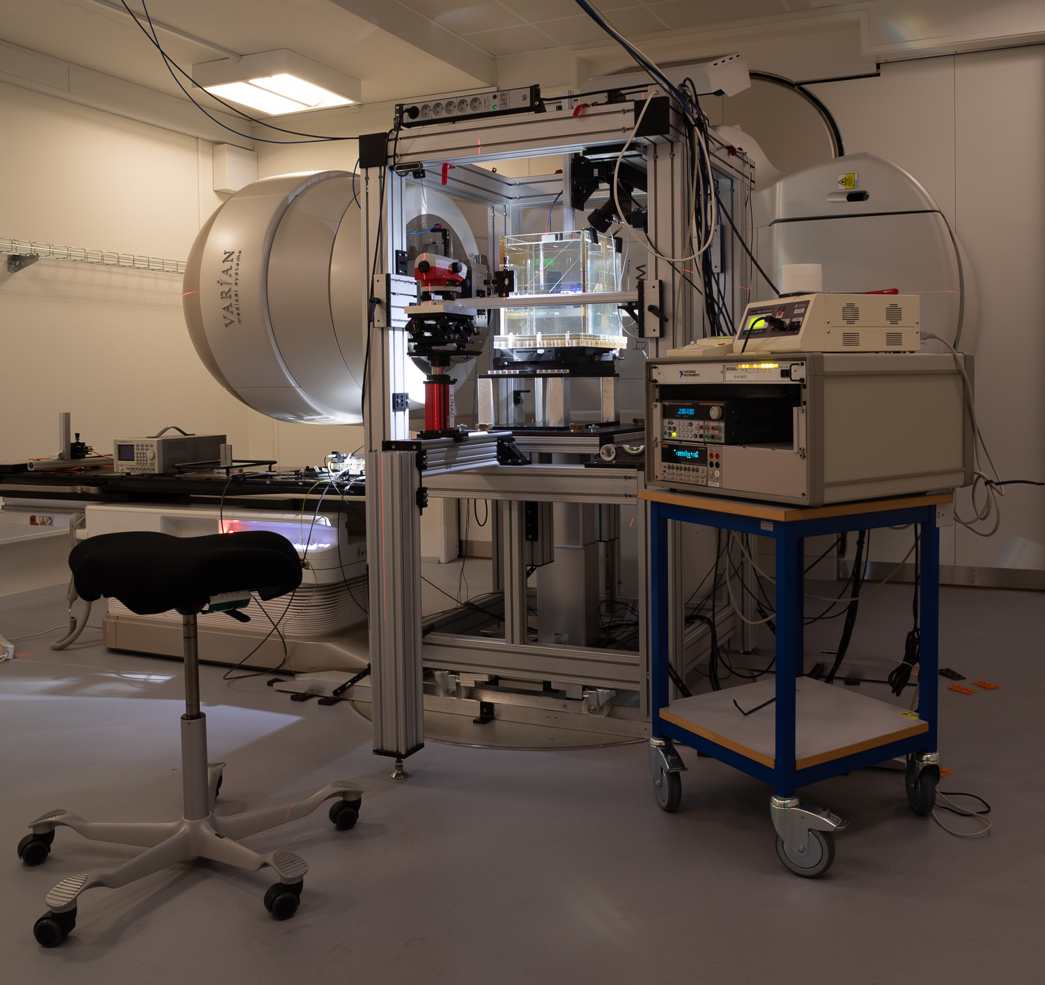
The rig used for irradiation of ionization chambers and other dosimeters in MV photon beams. The Ionization chamber position can be moved using and a motorized xyz stage with sub-micron resolution, The control box and its joystick is shown to the right in the photo above. The small rack to the right also contains a Keithley 2700 ohm meter for reading 8 thermistors used in the set-up plus a reference resistor.
Accelerator model: Truebeam from Varian Medical Systems.
Version: 2.0
Photon energies with flattening filter: 4, 6, 10, 15, and 18 MV
Photon energies without flattening filter (FFF): 6 and 10 MV
Electron energies: 6, 9, 12, 15, 16, 18, and 20 MeV
MLC: Millennium 120 leaf MLC (40 center pairs of 5 mm width, and 20 peripheral pairs of 10 mm width).
The accelerator iso-center is found before calibrations, and the distance from a reference plate is measured. The iso-center is transferred to the calibration rig using optical methods.
Calibrations are carried out with the water tank front surface 100.0 mm from the iso-center. This distance is realized as shown below using a calibrated 100.0 mm gauge block. One end of the block is positioned at the optical iso-center using an xyz motorized stage.The other end of the block is used for zeroing an indicator dial mounted on the accelerator head. When the water tank later is brought into position (see photos below), the water tank distance is then adjusted such that the indicatior once again shows zero. We therefore know that the water tank is at a 100.0 mm distance from the iso-center. A small adjustment can be applied, if a density-equivalent distance of 10 g/cm2is required.

For TPR20.10measurements, we use a 200.0 mm gauge block. All linac calibrations are made relative to an external monitor chamber (PTW 7862) mounted in a special fixture on the accelerator head. The temperature of the monitor camber is measured using thermistors on both sides of the chamber.

The water tank surface has here been adjusted just that the indicator dial is back at zero.

Ionization chambers can be positioned with high precision at the iso-center line with or without sleeves. The two black manual xy-stages shown in the photo below contain cross-hair that have been adjusted to be on the iso-center line at the start of the calibration session. During the calibration session, these two cross-hairs facilitate verification that the Leica NA724 telescope remains on the optical iso-center.

Low-level electrical measurements system
The key measurements in the medical dosimetry laboratory are carried out using ionization cambers connected to highly sensitive electrical measurement equipment.
We provide a calibration service for electrometer charge and current measurements..

Three electrometers systems are used for calibrations in cobalt and MV photon beams from the linear accelerator:
(1) The master electrometer is a Keithley 6517B electrometer with an external 1 nF low-leakage, air-filled, feedback capacitor. This air capacitor makes the system highly linear and stable as there is minimal influence of dielectric absorption normally found in other capacitors. Depending on the measurement task, the electrometer range can be set to 2 V, 20 V, or 200 V which corresponds to a maximum charge accumulation of 2 nC, 20 nC, or 200 nC, respectively. The system is calibrated in-situ against standards for DC voltage and capacitance, and the calibration therefore includes stray capacitance related to, for example, cables for the feedback capacitor. For DC current measurements, the charge accumulation is recorded every second triggered by an external 1 Hz frequency standard, and the linear regression slope of the charge vs. time recordings gives the current. With typical integration times from 30 s to 100 s, we can measure currents in the range from <10 fA to 6 nA. Current measurements in the femto ampere range are relevant mainly in the context of measuring cable and ionization chamber leakage.
A separate Keithley 6517 is used for the high voltage supply (up to 1000V), and the system can therefore be configured for floating or grounded measurements using connectors such as TNC, BNT, BNC/banana, or M-type.
(2) A second electrometer system identical to the master system described above is used for independent checks.
(3) A third electrometer system based on a Keithley 6514 electrometer is used for recording the output from a PTW7862 external monitor chamber used during measurement in the linear accelerator. An important feature of this electrometer is that it covers the range up to 20µC. A separate Keithley 6517 is used for high-voltage supply.
The three electrometer systems are controlled using MELab software, a general-purpose data acquisition system developed by DTU Health Tech. For current measurements, the recording of charge vs. time takes place internally within each individual Keithley electrometer using so-called buffered data acquisition. The three electrometer systems are synchronized to the same external 1.000 Hz frequency standard.
Water-tight ionization chambers are calibrated directly in water unless otherwise requested.
High-voltage settings
Ionization chambers are calibrated at the main voltage requested by the customer.
Measurements with LFMD ionization chambers are normally carried out using a high-voltage setting such that negative charge is collected. For PTW30013, PTW31021, PTW34001, and FC65G ionization chambers we use 300 V, for NE2571 chambers we use 250 V, and for NPL2611 chambers we use 200 V.
Recombination measurements
Special procedures have been implemented for measuring the initial recombination in cobalt, and the initial and general recombination in linac beams (Niatel methid). These procedures involve measurement of the ionization chamber current at different dose rates. The initial recombination is estimated by extrapolation to zero dose rate.
Links
- Association for the Advancement of Medical Instrumentation (AAMI)
- American Society for Testing and Materials (ASTM)
- International Bureau of Weight and Measures (BIPM)
- European Committee for Standardization (CEN)
- Danish National Metrology Institute (DFM)
- Danish Accreditation and Metrology Fund (DANAK)
- Danish Standards is Denmark's national standardisation body
- The European Association of National Metrology Institutes
- The Panel on Gamma and Electron Irradiation
- International Irradiation Association
- GEX Corporation
- International Organization for Standardization
- Medicoindustrien
- National Institute of Standards and Technology (NIST)
- National Physical Laboratory (NPL)
- Radiation Physics and Chemistry (Elsevier)